chris
-
Posts
1,256 -
Joined
-
Last visited
-
Days Won
78
Content Type
Profiles
Forums
Gallery
Everything posted by chris
-
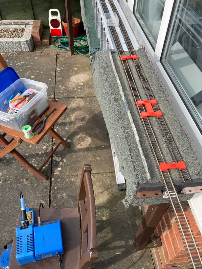
Update. I got the other two servos working with the DCC accessory controller. All three are now working. They are usually controlled by DCC commands. I also have push buttons to throw them. I've actually got two push buttons for each. One panel of two buttons is next to the crossover and the other panel with two buttons is adjacent to the siding turnout. This means I can throw the both the crossover and the siding from both locations without having to walk from one to the other. I like it a lot. This is an temporary solution, which, with a software update will be able to be switched to a new system I needed to get the double slip installed in Emble June. motorised. No point putting the car door locking motors back in or more DCC Accessory controllers. It was time to start installing a Layout Control Bus on Amblethorpe and transition away from DCC for controlling accessories. I've converted my tramway over to a Layout Control Bus last year, and have started installing one on ems mates layout. This means I'm familiar with the electronics side. The bigger challenge was getting a 10 meter cable out from my controlling Raspberry Pi to Emble June and installing the servo linking mechanism. The install went better than I expected. One of the servo linkages took a bit of time to get throwing, but the other there went in simply. I had and issue with voltage drop which mean there wasn't enough power and the Arduino switched off and on. One of the servos was working too hard. An adjustment to it's settings sorted the problem. But I think voltage drop will be a recurring problem. I'll probably change from 5volts to 12 and put in a 5v regulator on each node on my layout control bus. It's all installed under the baseboard. I'll find out how it deals with the outdoors. A plastic food tray is offering the electronics some protection. The whole setup cost less than £20 so replacing a component or two isn't going to break the bank.
-
Actually, for LEDs, you don't need to bother with full wave rectification, half wave rectification is fine. One diode off the black or the red wire will be fine as a power supply in this scenario.
-
OK. How many lights do you want to control? It sounds like just the directional lighting ie forward and reverse? If that is the case you only need two wires to control it. Remember that DCC function wires are switchable paths to ground. Normally the VCC is coming from the blue wire, but it doesn't have to come from the blue wire. If you can find a voltage from another place other than the blue wire, you can use it to supply the Anode of your LEDs and their cathodes can be connected to the white or yellow wires via a suitable resistor and your inter-car connector. You have track voltage in the trailer car. All you need to do is turn the ~14VAC of the DCC supply into a DC voltage for your LEDs. 4 diodes arranged as a bridge rectifier will do that. You could pop a capacitor in there to smooth the ripple off the voltage, you won't be able to see the effect, I don't bother when I use track power for LEDs. Again remember to put a resistor in series with your LEDs to limit the current. Start with a 10KOhm and if they are too dim go smaller, or you could do the Maths and calculate the resistance for the current you require!
-
I've got my first turnout working with a servo driving it. An Arduino is controlling the servo. It is listening and responding to DCC accessory commands and local push buttons. The main problem was getting the servo to connection to the turnout working. I used a wire in tube system proposed by IanR 10 years ago. The wire I had was too stiff. I bought some softer stainless steel wire and that works much better. The other problem was I'd got confused with my code and was making changes to the wrong servo, so not making any changes at all. I'm going away for a few days tomorrow, so progress will pause until next week.
-
I think Archies first explanation is correct. The "yellow" and "white" wires will be controlling transistors. These will be in a H bridge set up. A H bridge is usually used to control the direction of current through a DC motor to enable it to be run in either direction. In this digram the "yellow wire" would reconnected to Q1 and Q4 and the "white wire" to Q2 and Q3. VCC would be the blue wire and GND would be GND. There will also be some resisters in there to bias the transistors. The fact that function wires in DCC are a path to GND means that the resisters may be in a less conventional setup. But I can't be bothered to work out how. The connection to the trailer car are the inputs to the motor. The image has been taken form https://www.build-electronic-circuits.com/h-bridge/

-
I have a charter rake. It's an approximation of a WCRC. Does the job when I want a random loco puling something.
-
Before you lay the felt, have a read of this thread. Buy yourself a staple gun and some stainless steel stapes. Seriously, don't try and do this will a hammer and nails. Hard to see form the photos how much bracing you have under those boards. The big loop boards at each end will droop if you haven't got a good support structure under them.
-
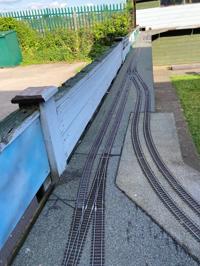
After a frustrating morning failing to get an Arduino to respond to DCC commands I switched to track remodelling for the afternoon. Emble Junction had two turnouts removed and replaced by a single slip. Trains can no longer snake through the three turnouts on the outer line which was always lovely to see. But the track layout is far more attractive.
-
I've been thinking about how to connect a servo to a point, outdoors. I still have a roll of PTFE tube from the car door lock motor installs and some stainless steel wire to go in it. What I've twigged on to is that the tube only has to be fixed in place firmly to work. The route it takes in between is irrelevant. This should enable me to place a servo under the baseboard and run the tube around the edge and on to the top. I've designed a small tube terminator mount and my mate has 3D printed it for me. The test board works fine with the turnout moving gently from closed to thrown and back. I've also developed a way of driving the servo from the DCC accessory commands. I won't go into details. I static tested it yesterday and it worked. I need to do some more field testing to check that it can still understand the DCC signals down the end of 10 meters of wire with trains generating electrical noise in the track bus.
-
I've been thinking about this a lot. I guess my work is more renewal rather than maintenance. But that is me splitting hairs. For me the frustration on this job is taking two steps backwards and only one forward. Although I'm now up and running again and it should now be good for a few years, there's still a ton of work to get back to where I once was. The backscenes need replacing. The station needs to go back in. The points need remotorising. All of this will just return me to where I was. The lesson here could be that I shouldn't let things deteriorate so much that it all has to be done at once. And when I do maintenance jobs I enhance the railway rather than just returning to as was. One enhancement will be switching from the car door lock motors to servos for turnout throwing. It is the next job to get on with. I've got a bit of code to adapt to control them, and I need to figure out a link mechanism which will work outdoors.
-
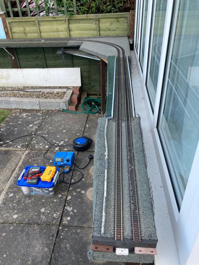
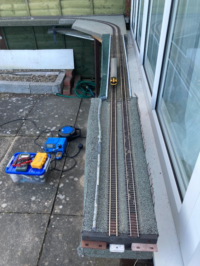
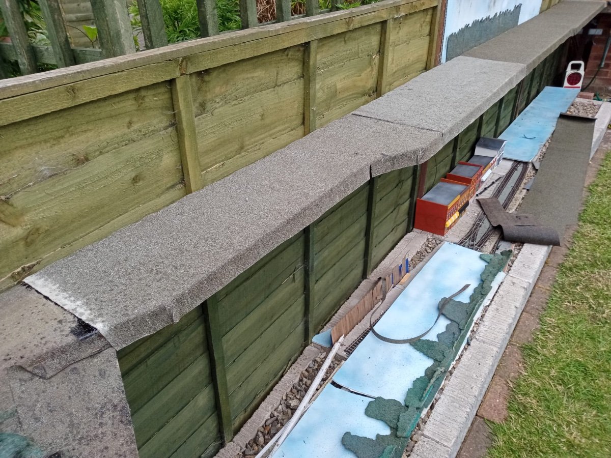
I decided to add roofing felt to the top of the viaduct. previously I was concerned that the adhesive wouldn't play nicely with the plastic. The plastic wasn't doing that well exposed to the elements so I decided to add the felt. Went down OK and looks much better. I risked gunning staples into the felt and thus the plastic. They seemed to go in OK. The edges got stapled every 10cm or so. Yesterday, once again with the assistance of my friend, the track went down around the curve and over the viaduct. I'd had enough of soldering old rails. My friend gave me 4 lengths of long straight track as a like for like replacement for the tracks on the viaduct. It was a still evening so soldering wasn't too frustrating for once. The old track will be fine for indoor use. With the tracks down and soldered I was up and running again. Only one bond was a failure and that was quickly resolved. Thinking about it now, to have a dead section, there must have been two failed bonds. The other may be in the point work. probably easier to ignore. Had some friends round for drinks yesterday evening and ran trains until dark. Track performed exceptionally. Probably the best running session I've ever had. I don't think there were any incidents caused by the track and we were driving 3 trains at a time continuously looping for a couple of hours. The trains and the drivers weren't as perfect as the track and there were a few driving incidents! A mate bought his class 20 round and it wasn't running well, making an worrying noise when driving bonnet first. When we coupled some wagons to it I noticed the buffers were missing. It appears that one of my mate grown up children has dropped it on his garage floor and failed own up to it.
-
frustrating day soldering rails that have been outside for 11 years. I did the vast majority of it inside at my desk, but that didn't make it any easier. By late afternoon I was ready for track relaying. I persisted and got the track down the full length of the straight, soldering in the last bonds that I couldn't do inside. There's still more to do, but we are away for the weekend, so it will have to wait. Monday's running session may be a bit different.
-
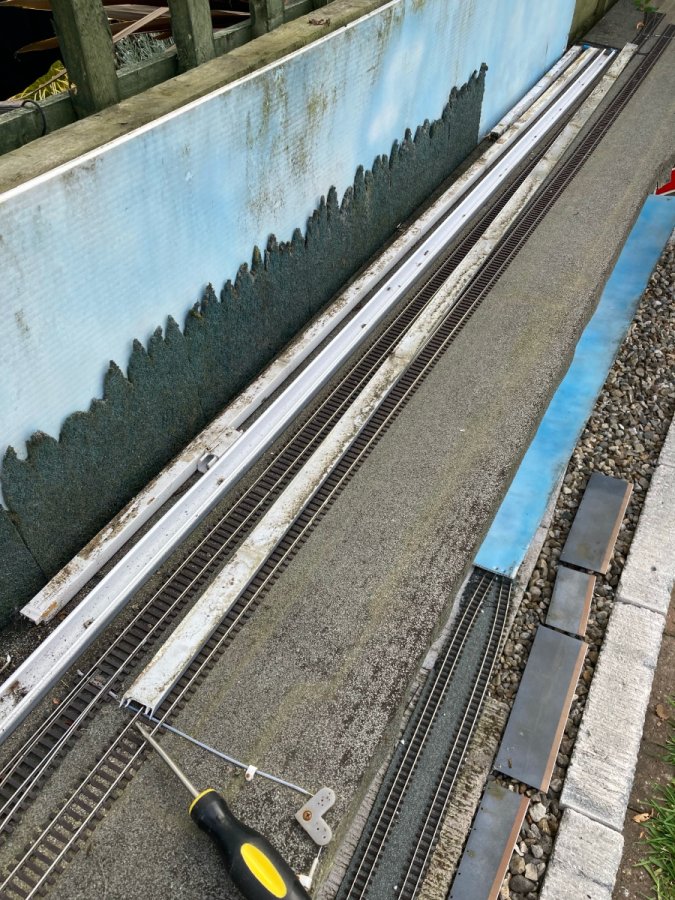
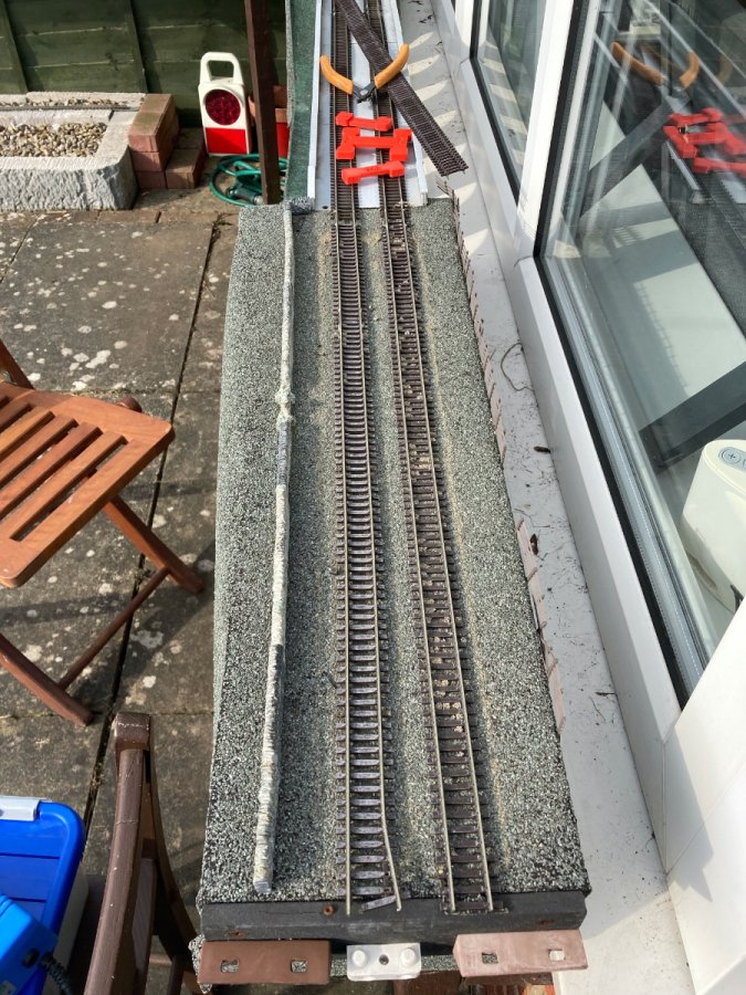
I'm adding a layer of felt to the long thin board. The ply under that felt is as goo as the day it went in, 12 years ago. I've found that the key is to ensure that water cannot get to the sides of the boards. As long as the felt hands how below the bottom of the board I don't have any issues. Also joins in the felt have to overlap. The only issues I've had is when I've not followed those rules. Personally I like the look of the felt, preferring it to wood. It has the appearance of ballast. While helping yesterday my friends decided that he liked the texture so much he will use felt in the depot of is loft layout. You can paint it with enamel if you are so inclined. Yes to bracing. I use Aluminium T orders either from old conservatory roofing or greenhouses. Lightweight and strong.
-
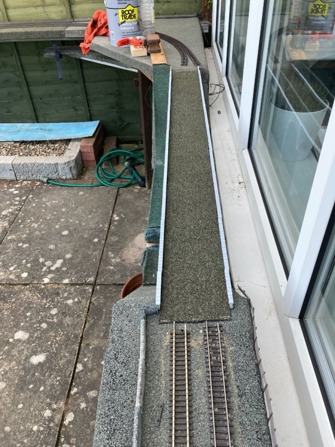
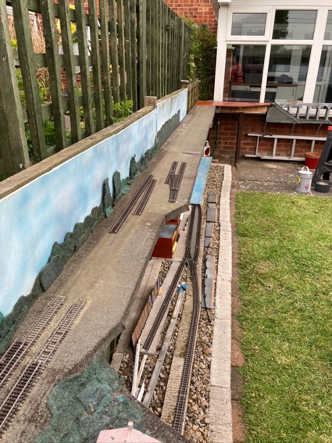
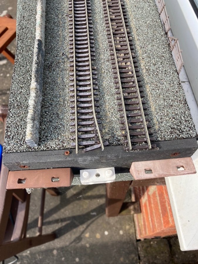
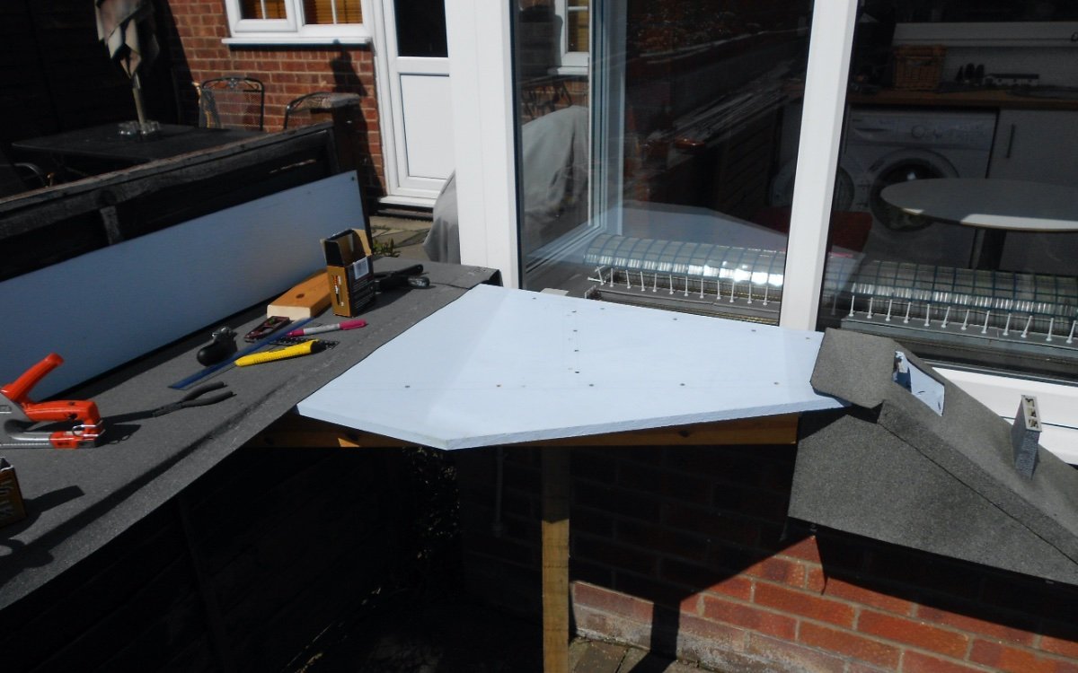
Track was lifted yesterday evening. The new section of baseboard went in. I covered this board with felt before I installed it. The photo shows it with as layer of adhesive on ready for the second layer of felt. I had some help from a friend. we managed to get a second layer of felt on the baseboard where the track had been removed before rain and lunch stopped play. I'll try and get the track back down this evening.
-
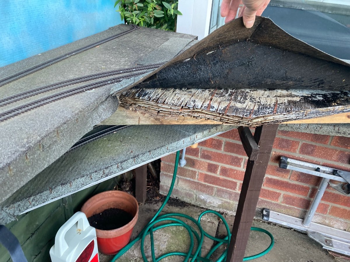
The problem was joins in the felt. This was made more of an issue by the felt joins being near board joins, so was water could get into the sides of the ply. When I put the new board section in tomorrow I'll put on two layers of felt so ensure that the there are no similar problems this time. I've got a small section of plastic baseboard next to the start of the viaduct. Again the idea is to keep water away from the end of the ply. The felt here is over 10 years old. So while I'm working on it I've decide to lift the tracks and platforms and put a second layer of felt on. Should keep things in good order for a few more years. The linkage from 8th point motors to the turnouts were failing, so I'll install them in a different way.
-
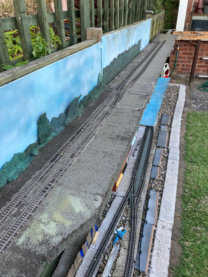
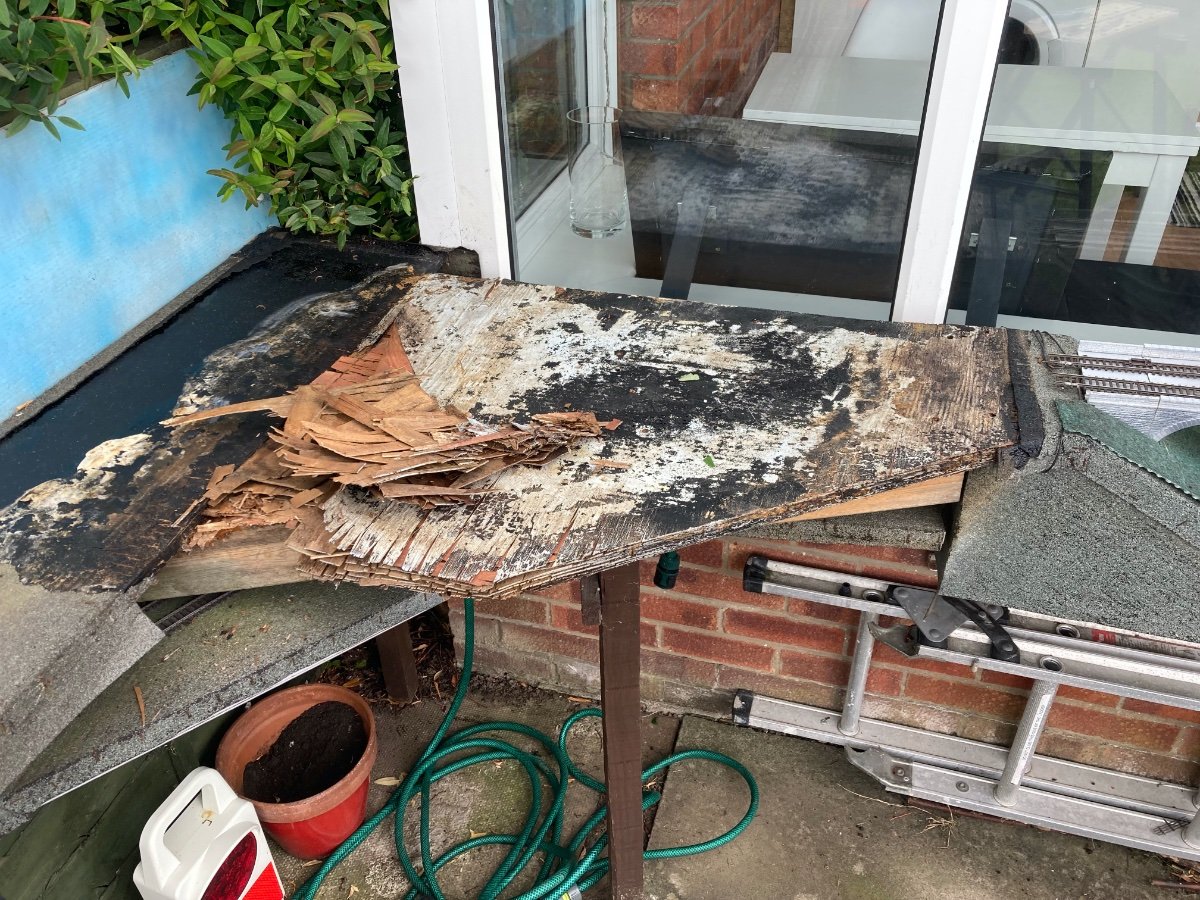
Today I've removed the delaminated baseboard and got ready for the replacement board to go in. Fortunately I remembered to measure at this moment so the replacement board should be about the say. the scenery is made to measure on this section. As you can see it was in a bad way. The support structure is OK. I've cut a new piece of 18mm ply and given it a couple of coats of exterior wood plaint. Tomorrow I'll stick the felt on and put it in place. I'm then going to put another layer of felt on top so non of the felt joins are exposed.
-
Yesterdays running session involved the very rarely used, track over the void reversing curve out of Colwick platform 4.
-
I dinked my track when removing the lift out section. No point fixing the track. Easier to replace. One advantage was, that although the section to the viaduct is short I had used two pieces of track. Replacing with one length means there are a couple less track bonds to fail. I took the opportunity to realign all four of the track ends to improve running through this notorious derailment black spot. Hopefully it will be sorted for this years running season. This afternoons and evenings sessions will be a good test.
-
My track has been down for a decade. There are places where the baseboards have turned to paper! Trains run over them fine even though the track is basically unsupported. More of a problem is where the baseboards have sunk. I cannot see with the naked eye that one section of board is lower than the next so the gradient is very small. But some of my trains really struggle on these unintended climbs.
-
With DCC I can run more than one train per track. The max I've had looping a round Amblethorpe is 6. I think there were 4 drivers present at the time. Most of the time I'll peak at 3 trains looping. It adds a bit of fun when two people are driving trains on the same line and have to ensure that they don't catch up with the other train.
-
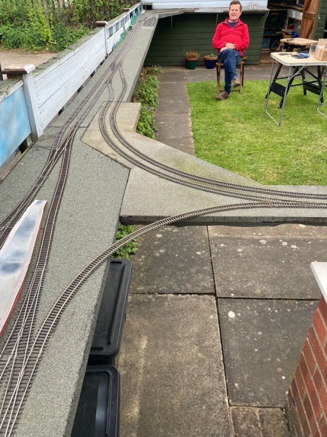
I've been thinking about how I run trains on my railway and comparing that with how I thought I'd operate. I have a 20+ meter twin track loop. Off this there are two terminus stations, one inside the loop and one outside. They face each other so a train can run form one terminus to the other, either directly or by running round the loop as many times as the operator likes. There is a through station on the loop. This has a crossover and a siding to enable trains to terminate there and then get out of the way. My plan was to run my railway end to end as much as looping. However, as I have commented elsewhere, the vast majority of my running sessions simply have trains looping round. I've come to the conclusion that garden railways are not about "operating" trains, but letting them run around and around and around. I'm interested in what other people think. Could we start advising people to keep their garden railways simple and recommend that they make themselves an additional indoor layout if they want operating kicks.
-
Have a go at re-enforcing it. Try drilling a hole vertically through the parapet and into the block below. Then put a rod of something rust proof in the hole and fill over the top. You've still got loads of earth wire from the twin and earth cable haven't you (I have), that'll do the trick.
-
I used to put some silicon grease on the springs to prevent rusting. Fallen out the habit. Now have rusty springs!
-
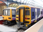
Hello and welcome. 47401 has been know to visit Colwick Station.
-
Teaching through photos I came across this, a scene from 9 years ago today. This section of baseboard has not fared well. Today it look like this! I have a sheet of 18mm ply ready to to replace it. After Monday's running session I plan to make a start on replacing it. I visited an actual model shop today. First time in over 2 years. Was there for some brass tube and rod for a scratch building project and also picked up a long crossing to enable a junction remodelling.