


stevesoar
-
Posts
18 -
Joined
-
Last visited
-
Days Won
1
Content Type
Profiles
Forums
Gallery
Posts posted by stevesoar
-
-
Hi, yes I have a box full of old stuff, always try to re-cycle if I can although these are not ideal being metal, however
they prove that the system of buffer charging works.
Thanks for your response, much appreciated.
regards
Steve
-
Hi, I have now made a prototype using a simplified circuit which charges from a buffer stop into the loco buffers
these are modified to steel with leads going into the on board control circuit. The track buffer stop is modified with molibium magnets
3mm dia x 3mm long. these make good electrical contact with the loco buffers, the buffers have a few mm movement to allow for poor alignment.
the loco can be recharged or set to run by the changeover switch. If the loco is running towards the buffer stop and the switch is set to charge
then the loco switches off soon as contact is made and recharge starts.
Hope the photo makes sense, let me know if interested in more clarification.
best wishes to all
Steve

-
 1
1
-
-
Hi, my latest prototype circuit, the top diagram shows circuit in charge mode via 2 pin socket, the lower diagram shows run mode, the DPDT switch
can select either charge or run.
When in charge mode the FET is biased OFF and when in the run mode the FET switches ON, the loco can be unplugged and driven away.
So, no mechanical or reed switches on board, just the 2 pin socket.
Will be further testing the prototype this week, will post results. In the meantime if more info is needed please ask.
best regards to all
Steve
-
Thank you for your comments, much appreciated. Supercapacitors are improving all the time so yes, all we have to do is wait for the technology to catch up.
In the meantime the li-ion battery is probably best choice. I have several locos with PP3 li-ion batteries which give 3 to 4 hours run time.
regards
Steve
-
Hi, your comments are very valid, I want to reduce the time waiting for battery charging, and eliminate the complexity of on/off switches. The future of supercaps is looking promising with a lot of research to increase the capacity to rival battery technology, I believe graphine is being considered in the manufacture. If/when this happens then the capacitor can be treated like a battery but with very fast charging, I think that the wheel pickups might be insufficient so might need a plug in for the higher charge current, or else it would be little different to the battery. I like to look at new technologies and it is great to have feedback, thank you for your input.
I like the idea of being able to leave the loco on track, in a siding or loco shed etc. the other "live" sections might be at stations or level crossings so that the loco can charge whilst waiting.
I am still using the Poover PP3 battery with good results, it has excellent protection for over discharge damage and I have a loco without an on/off switch, charges up in a powered siding and is allowed to slowly self discharge when not being run, can be stored and when self discharged is protected by the inbuilt battery protection circuit. Could be a bit fraught if the transmitter is inadvertently switched on ! Any comments or ideas much appreciated.
It might be a no brainer but then many ideas start with a no brainer.
Thanks for your interest
Steve
-
Hi, I have simplified everything, instead of a battery I have 4 supercapacitors 15F 2.5V each in series. This gives 10V which is boosted to 12V for the receiver. Capacitors are charged thro the loco track pickups from a 1metre section of powered track, rest of the track is unpowered. The capacitors charge up from the track via an onboard bridge rectifier, full charge in approx 15 seconds.
Loco is top up charged each time it runs over the powered section. The distance run between charges is approx 12 metres so larger layouts will need more 1 metre powered sections.
1. only need to keep the 1m track charging sections clean.
2, no on/off switch needed.
3, no waiting time for charging.
4, very simple circuit.
Still early days.
regards to all
Steve
-
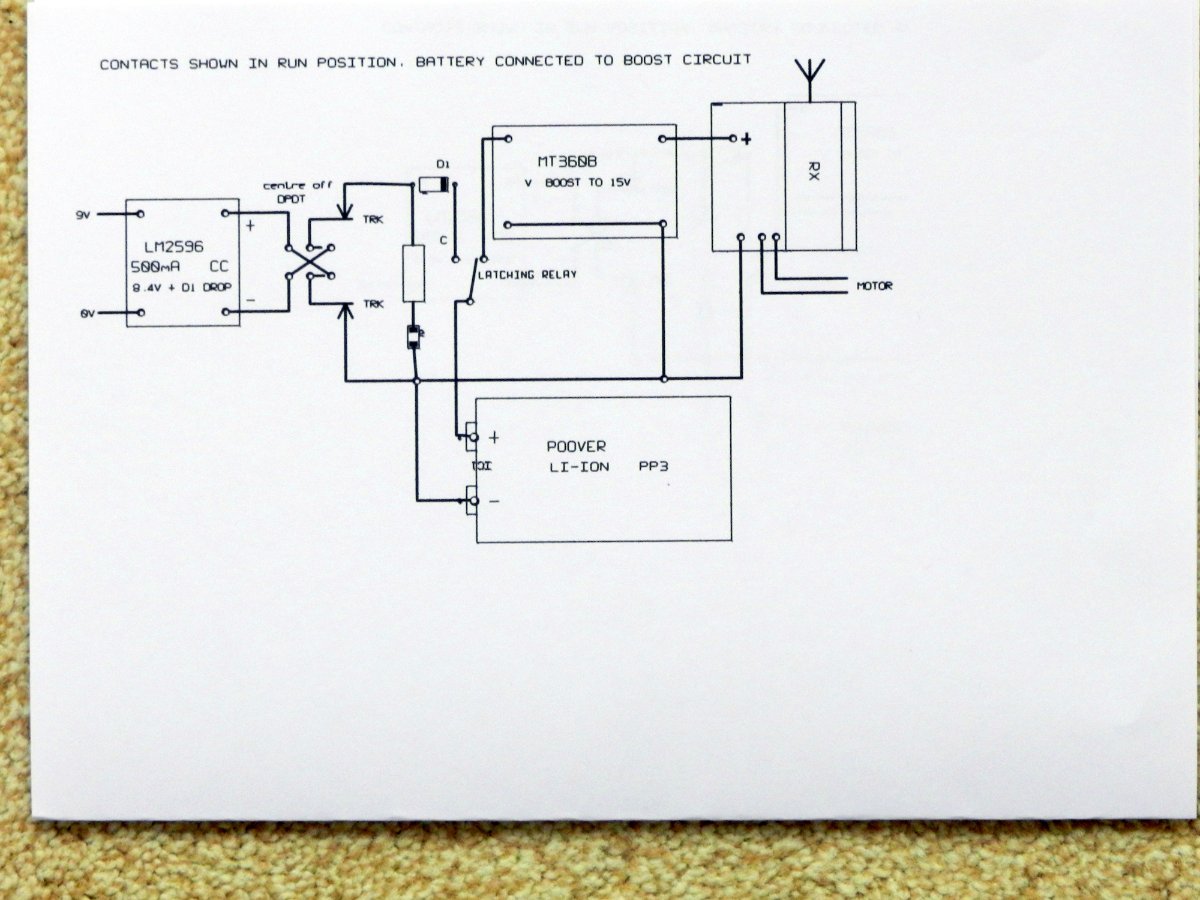
Hi, I have made some "improvements" to the track charging circuit, it now has a centre off DPDT switch the circuit is shown in the RUN position, the loco can be driven off the charging track, the DPDT switch is switched to the centre off position
when the loco is ready for a charge it is driven back onto the powered siding and switch is set to charge position, this flicks the relay contacts to charge and isolates the electronics, when charged the switch set to off and as the loco is also off it will retain the charge and can be stored with a full battery. It can be switched on again by switching to the Run position.
The Poover battery gives about 3 hours run time, it has inbuilt protection for overcharge, undercharge, overtemperature, and cell charge balance.
I have two locos with this system and they can be charged at the same time on the track. The running track must be "dead"
hope this all makes sense.
Best wishes to all
Steve
-
IPA is good but has anyone tried K2 contact spray? I don't have an outdoor layout but my unheated garage is pretty cold and dank. I have used K2 on DC, DCC and more recently on RC control with track re-charging.
I have also used K2 on electrical and electronic circuitry to keep contacts clean.
worth a try?
Steve
-
just a follow up, I have reduced the boost voltage from 15 to 12v, and repeated the 10 seconds per lap run.
run speed 71 miles
duration 1hr 50 mins.
distance traveled 130 miles
this has made the system more efficient, any thoughts on this?
-
I have been testing the EDL PP3 li-ion battery 600mAh, tested on a 4.6 yard loop and setting time/lap and running until battery is flat.
10 sec lap (scale speed 71mph) 1hr 20min 94miles range
11 sec lap (scale speed 64mph) 1hr 30min 96miles range
16 sec lap (scale speed 44mph) 2hr 30min 110miles range
I have ordered some Poover PP3 batteries 700mAh these should perform better.
Test loco is an old Lima Deltic, lots of room to play with.
-
Hi, as promised here is a rough diagram of my on/off switching circuit. The li-ion charger is a cheap 2 cell (8.4V output) the DPDT switch feeds onto the rails and
can switch the polarity, when the top rail (on diagram) is positive then the relay is set and the battery is connected and charges via The schottky diode , The receiver is also powered and active.
If the switch is flipped to reverse the polarity, the relay is unset and the battery disconnected, the diode protects the receiver. The loco is now off and no drain on the battery.
The relay is a single coil latching type and only requires a pulse to set or reset, hence the capacitor feeding the coil.
hope this makes sense.
-
Hi, between 1 and 2 hours depending on speed and load. Still in prototype stage, recharge in approx 1.5 hrs.
-
Hi, Thanks for the interest, it's going to be difficult to explain it without a diagram so I will create one and a description. In the meantime I attach a photo of my proto.
The pale, rectangular block on the rhs is the latching relay which selects the run/charging mode. Also on top is my receiver, and on the side the charger circuit and boost circuit to take battery voltage up to running voltage.
the orange and black leads on rhs go to the short section of powered track it is these leads connected to a 12V supply via a changeover switch, selects on (charging) or off . The red and black leads on the LHS go to the motor.
The whole lot sits on a PP3 li-ion battery (you can see the terminals just below the relay).
Hope I have not caused too much confusion,
Steve
-
Hi, just been experimenting with a few ideas on battery charging. I have decided that a powered siding (12V dc) and pick up through the rails suits me best, an onboard buck charger output 8.4 volts to
charge an EBL PP3 2cell li-ion battery, a boost circuit raises the voltage to 12v for loco control.
I have replaced the loco on/off switch with a small latching relay TQ2-L-5V this is wired to isolate the battery if the rails supply is reversed, a blocking diode protects the buck charger circuit.
So the loco is run onto the powered siding and starts to charge, I turn off loco lights to save energy, the loco is still powered up and can pull out of the siding and onto the dead track at any time.
When fully charged a trackside led changes from red to green. Now if the track voltage is reversed the onboard relay latches off and the loco battery is isolated.
To turn everything back on again the siding is powered up and polarity selected to set the onboard relay. Loco is now active and can be driven out of the siding and onto dead track.
So loco can be run, recharge and switched on and off without having to fiddle with a switch on the loco or having to remember where the magnet is. All this can be done without going anywhere near the loco.
If required the siding can be long enough to accommodate more than one loco.
I don't know if this has been done before, perhaps it has? I can send more details if anyone is interested.
-
1
-
-
The best thing about being retired is no pressure to earn a living. I agree hobbies are to be enjoyed, thanks for the well wishes.
-
As I said I am retired so this is only a hobby for me which I thought might be of interest. The protocab looks good, thanks for the link.
-
Hi, I am a retired electronics engineer and I have just finished the design of a radio control for 00 gauge, using a Li-Ion battery I am getting good results, my test track is not powered so that there is no problem with dirty tracks.
The charging can be done externally or via the wheel pickups, the loco can be run onto an isolated powered siding.
The electronics are very simple, utilises 433Mhz four control button keyfob to select forwards, reverse, accelerate and decelerate. Multiple locos can be run on the same track and reverse loops are a piece of cake. At present
the battery+receiver will only fit into diesel locos (mine are class 31 and 35) running time is about 1 hour depending on speed. Forwards and reverse lighting is included .
I have other non battery variants of this for indoor powered track.
hope this might be of some interest,
regards to all
Steve Soar


radio control for 00 gauge
in Train Control
Posted
Hi, have made some improvements, smaller magnets (2mm dia x 3mm long) these can be better concealed and allow the loco to pull away without assistance.
I have also remade the buffer stop in plastic and concealed the wires, still prototype stuff but works well. Just needs a bit more refinement.
regards to all
Steve