

Clay Mills Junction
-
Posts
388 -
Joined
-
Last visited
-
Days Won
28
Content Type
Profiles
Forums
Gallery
Everything posted by Clay Mills Junction
-

Operating Points Outdoors
Clay Mills Junction replied to mainthreadmartin's topic in Electrics & Wiring
Has anyone any experience of using angle cranks between point motor and point. I'm looking at using the MP1 point motor mounted in a box on the back side of the concrete block but this would give me a vertical movement that would need to convert to horizontal to move the tiebar. There seem to be a couple of angle cranks "off the shelf." GEM 1012 angle cranks (Mercontrol) seem to be out of stock, is GEM even in existence? DCC concepts Cobalt angle cranks (for those with bottomless bank accounts) Make my own. Does anyone have any advice on how would I go about making my own please? I was thinking I could use plastic servo arms with two of the arms cut off. I'd then just need a mount to go on the corner of the block. The MP1 motors are fairly strong so I don't think they'd need to be perfectly resistance free, just not seize up (I have plenty of oils and greases for cars and bikes. -
Glen Dollar Garden Railway
Clay Mills Junction replied to Clay Mills Junction's topic in Members Garden Railways
Since there is a recent picture of the viaduct, there will have to be some maintenance happening here in spring to clean the stones and bottoms of the viaduct supports. I'll also have to tone down the white of the glue somehow. The viaduct does need some walls either side of the track and I have looked at the possibility of making them from the off-cuts of concrete block. However, given the trouble Mick has had with pigeons and the difficulty in making them, I'm more inclined to use my favoured 15mm L section aluminium bent to shape. So I think the plan will be to wait for warmer weather and use the blow-torch to bend the aluminium to shape, glue it to the block with a slight overhang and then use paint to get it to a similar shade to the block. -
Simple MP1 servo point motor wiring.
Clay Mills Junction replied to Clay Mills Junction's topic in Electrics & Wiring
I've decided to abandon the second set of switches at the motor so I can go digital at a later date. That means my 7 core will take the common positive and 3 pairs of switched negatives. I originally bought 3 motors and I set one of them up on a spare piece of 9mm ply along with an unused SL-e91 point to test. I've settles on 9v as being optimum. Unfortunately, best laid plans and all, I've bought 6 more motors and used 5 of them on my Dad's layout due to space constraints under the board. I've also switched in my 1A power supply as more lights were added up there, leaving me with just a 0.3A power supply for this. The next task will be to make and wire up the control box to the 7-core and 3 motors to the other end to test whether voltage drop is an issue or if there is interference that could cause an issue with the wires being bundled. -
Glen Dollar Garden Railway
Clay Mills Junction replied to Clay Mills Junction's topic in Members Garden Railways
I didn't expect the viaduct to cross an actual water feature.
-
I hope everyone has a great Christmas and a merry New Year. Let's hope 2024 brings weather more conducive to running trains outdoors.
-
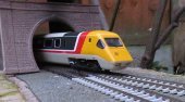
So I've bought a pair of the new release TRSB coaches for the APT set. As put in the GlenDollar thread, my intention was to sell one on and make a 2-PC-5 rake. With the opportunity to take some photos of it while I have the set, it would be rude not to. I was tempted not to try to sell it having looked at it on the window sill, but looking at the photo I took in the garden in the summer, it'll be too long. My intention was that everything I run will fit through the inner line of the loop with the exception of the HST set, that means the APT can be max 8 cars total. APTs generally ran as two sets together, a full set would be 7 cars: Driving Trailer Standard - Trailer Standard - Trailer restaurant standard buffet - Trailer unclassified - Trailer First - Trailer Buffet(?) First - Non driving Motor. A 14-car train would therefore be two sets with the NDMs connected. It seems, from research, that the number of times 2 full sets ran together was actually pretty limited. The reality was that, in service, mostly they ran as one full set and a short set. The short set would be minimum DTS-TBF-NDM but could have a TRSB. Making them 10 or 11-car trains. I can't see may times they ran without the second NDM except in testing. A model railway is only ever a representation of a real train, we try to get as close as we can but there will always be compromises. So with that in mind, here are some photos of different configurations with what I have. Symmetrical 4-PC-4 3-PC-5 As I'll run it 2-PC-5
-
Glen Dollar Garden Railway
Clay Mills Junction replied to Clay Mills Junction's topic in Members Garden Railways
Yep, it fits between the points with enough space not to impede the other line. There will be enough space for a platform that accomodates all 7 coaches, if not the class 43's. -
Glen Dollar Garden Railway
Clay Mills Junction replied to Clay Mills Junction's topic in Members Garden Railways
Yes, its becoming a very expensive hobby. I'm going to be thinning my stock out by selling a few things on ebay I think. The HST is older coaches (c.2014) with lights. They are currently going for big money on ebay but I picked a couple up that had their lights removed for lots less. It won't cost me as much to install lighting back again as I saved. There are cheaper ways if you are prepared to accept less detail and/or do some work. Making Tracks is something I'd like to see, current thinking is to go and see it at the Great Electric Train Show. Good you had a good time watching it. -
Glen Dollar Garden Railway
Clay Mills Junction replied to Clay Mills Junction's topic in Members Garden Railways
It has been so wet this year I've hardly managed to get out into the garden to keep the place tidy, never mind getting anything running. Some spare time this evening I managed to get the HST and APT sets out. I bought the final two Mk3 coaches for the HST set so I now have a 2+7 set and I wanted to see how it fitted into the passing loop station, my calculation was that it would fit but by how much. Also I wanted to see if the APT set would fit in the inner loop and whether it could take another coach. Here it is in 4-PC-2 formation. Unfortunately, the extra coaches come in packs of two and I think that 9 cars will be too much. So perhaps I will buy a pair of TRBS (restaurant buffets) and try to sell one on. Latterly, they ran in shorter form (6-PC-PC-2) with only one TRBS in the formation, I may be lucky and find someone who wants to do the same.
-
Definitely nice to see some trains out in the garden after all of this weather. I'm hopeful of getting something running in the next few weeks.
-
So an interesting evening, started with a bang, literally! A thunderstorm, the most violent I've ever witnessed and demonstrated by the sheer number of strikes in the area on the tracking app, hit within metres of the house. I thought the bang was inside and the thunder was immediate but it was only because I'd left the back door open for air. Although it only knocked out the electricity for a split second, it has knocked out my internet. The phone line still has a dial tone, so I'll have to get that reported tomorrow.
-
That sounds like it would work. Using traditional baseboard joining techniques to align the boards. Scaffolding timbers are likely to be fairly long lasting, my concern would be how flat they were along their length and if there was any twist to them. That might be something that a plane might be able to flatten out, I don't know since I haven't used them. One of the things with railways in the garden, there is no "the way to do it." Everything is a bit of customisation and trial, somethings that work in one garden or scale might not work in another.
-
Hi Binky, Welcome to a not very busy forum currently. I'm sure What you want to do is perfectly possible. I guess there are a few questions to cover like, what kind of height above ground are you thinking of and what features will you have e.g. bridges. Given you'd be putting it away when not in use, you might have an easier time using wood than most, with much less protection needed to prevent warping. Maybe even a traditional braced ply approach like indoor baseboards. How dry is your garage? You'd want it to have some moisture resistance in case a pesky shower came along and to save you having to remove it at the first sign of rain. For that reason I'd recommend some height above ground level, even if it is just enough to keep your boards off the ground so they don't soak up ground moisture. What you might want to consider are some permanent mounting points to provide a solid anchor for your temporary boards to mount to so nothing moves if it gets knocked by you moving around?
-
Hi Paul, If you are usinng arduinos then you're already beyond my technical knowhow. I probably did go through a similar thought process though. First thought, will you have enough power for everything you want to do? I have no idea what the arduino is capable of supplying. I've only got 2amps to play with so I've gone for separate power supply for accessories. A lot will depend on how much stock you can run simultaneously. Slow action point motors like Tortoise or Cobalt consume power even when not being operated where the MP1 motors I'm using shut off completely. My second thought is about weather resistance and longevity outdoors. Given servos get used in lots of applications like model boats and planes, they must have a certain hardiness to them, though that probably doesn't equate to being left outdoors. Comparatively expensive circuit boards may need preventative weatherproofing unless you make them removeable? Again, outside my experience but one reason I've not gone down the route of digital point control. I believe from talking with some people from MERG that ordinary servos need a controller where you can set the travel limits, probably what you need the arduinos to do. The MP1 motors I'm going to use, have a pin in the cam to adjust the movement. The cam also has internal cut-offs to stop the motor at the correct place so can be activated by a simple switch or the other thing I'm considering is a Hornby R6010 bluetooth accessory decoder, if and when Hornby ever get around to releasing the app on Android and assuming it works OK.
-
I think Mick, being a bit of an ornithology fan probably wouldn't want to hurt a pigeon, even though they are classed as pests. I, on the other hand, wouldn't have any compunction about creating pigeon booby traps.
-
I started a thread on the topic. I think you need to do something periodically. Various choices exist.
-
Simple MP1 servo point motor wiring.
Clay Mills Junction replied to Clay Mills Junction's topic in Electrics & Wiring
Thanks Chris. I may have used the wrong terminology for the switches, I meant sprung ones that return to the centre (off) when not being pushed. I've got the spec sheet for the motors from the manufacturers website. http://www.mtb-model.com/files/produkty/MP1-setup_CZ_EN_DE.pdf The motors are mostly mechanical, a cam inside them physically disconnects the switched negative at the end of the run a so there isn't any need to set the end of travel or have a precise cut of the power supply. Connecting both switched negatives at the same time causes the motor to shuttle back and forth continually. The motors are quite noisy although that doesn't bother me outside, I wasn't worried about being able to see them throwing -
How best to create trackbed
Clay Mills Junction replied to Robin's topic in Layouts In the Planning Stage
Hi Robin, Welcome to the forum. I would think that wood will depend on the type of wood and its proximity to the water. If you were using wood to raise the track level above the slab level then that might be OK. Certainly, the bridge by the waterfall I would look to make out of metal if you can. I'd echo Mick's comment on the curve sharpness. Even with setrack second radius you might end up cutting the corner a little and having to support the track. Really you want curves to be as gentle as possible so 4th radius would be preferable. Good luck with the project. -
Simple MP1 servo point motor wiring.
Clay Mills Junction replied to Clay Mills Junction's topic in Electrics & Wiring
There is 7-core automotive/trailer/marine cable that isn't too expensive. Comes in 14A form with the individual cores being 24/02. I'll buy some and see how it goes. If I use the 7-core for the 6 switched negatives, I've got plenty of 2-core that I can use so the positive and negative running down to the local switches can be separate. -
Hello from Lancashire
Clay Mills Junction replied to Allegheny1600's topic in Welcome & Introductions
Hi John, Sorry to hear you and your wife have had a tough few years and I hope your building of a new life goes better and you find somewhere that suits your needs with space for a garden railway. I suppose the only thing I can advise, I guess if you were willing to up-sticks to Greece that you aren't tied to a particular area of the UK, that there are areas of the UK you can get a lot more for your money than other areas. Best wishes, Barry. -
The video editor in Windows seems to have finally been removed by stealth in an update. However, the replacement, Clipchamp seems OK but is also an online app.
-
Glen Dollar Garden Railway
Clay Mills Junction replied to Clay Mills Junction's topic in Members Garden Railways
Quick video to show how much flatter the cemented in blocks are. Just a little fettling to do then on with the roofing felt. I also managed to get the damaged track in the siding on the board replaced. -
Glen Dollar Garden Railway
Clay Mills Junction replied to Clay Mills Junction's topic in Members Garden Railways
That is the cementing of the station area and transition onto the viaduct done.
-
Simple MP1 servo point motor wiring.
Clay Mills Junction replied to Clay Mills Junction's topic in Electrics & Wiring
Questions. What voltage should i use? What grade of wire will I need given the power requirement and length of runs? Could I bundle them, say a 6 core cable with just the switched positives in it? I'm thinking the power supply wires could be separate as they might go around and power other things at the same time like lights. -
I've bought three of the MTB MP1 point motors I mentioned in my garden railway journal. The motors are very strong, there is no way to move one without powering it. The up side of that is the point can be guaranteed not to change with no power supplied, so no need for a constant supply; the downside is that I'll need to duplicate the control for it at the controller and locally at the point itself. I'm thinking I'll need to send 4 wires to the first point and two more for each further point. Sending the permanent positive to the local switches along with the switched positives. A SPDT push to make (don't know if that's the correct term) switch for each point at the controller and again at the point. The blurb says the motors are 150mA max draw. I've tested at 13v DC and the draw is about 120mA. The lowest it will operate appears to be 6v with much lower power consumption, less than 90mA. It still seems strong at 6v though takes about 3 seconds to move as opposed to 2 seconds at 12v. I tested at 5v and it wouldn't move at all. Questions in next post.


