mainthreadmartin
-
Posts
10 -
Joined
-
Last visited
Content Type
Profiles
Forums
Gallery
Everything posted by mainthreadmartin
-
Hellidon Garden Railway
mainthreadmartin replied to mainthreadmartin's topic in Members Garden Railways
A quick update. Sadly as of last October I was put under threat of redundancy and in Jan this was made official. As of 21st April I will be redundant. So, my thoughts have not been on the garden railway of late and until I am back in employment the project is on hold. -
Re Computer Control Check out RocRail as this is a nice bit of Open Source software that is very like Railroad & Co TrainController. Look here :- http://wiki.rocrail.net/doku.php A bit simpler to use than JMRI - I only use JMRI DecoderPro which is terrific.
-
Operating Points Outdoors
mainthreadmartin replied to mainthreadmartin's topic in Electrics & Wiring
Ian, Excellent info - many thanks. I will certainly be adding the extra wiring to my outdoor points as you suggest plus making up some little boxes to house the points themselves as per your template. -
Hellidon Garden Railway
mainthreadmartin replied to mainthreadmartin's topic in Members Garden Railways
Mick, Thanks for confirming that my planning will stand me in good stead. In the past I have tended to rush into getting something up and running but with this project it is going to be a bit more paced as it needs careful construction to get the best from it. I am trying to think through the building process so that I assemble the tools etc I need before I get stuck in, so getting a laser level and long spirit level are going to be needed at the outset. The shed will be used for storage of the felt and smaller stuff so that needs to be the first item to construct. I am hoping to get the shed up Aug or Sept and some foundation work started soon after, certainly before the weather gets too bad this year. I will be documenting the whole project very fully as I want to create my own web site for it, with links to here of course. I wouldn't agree that your SGR is rough and ready, in fact I have looked at several garden railways over the past few years and always wanted to do my own but was a bit put off by seeing completed and very complete examples. You inspired me to get started because I could see how you had begun and thought, Yes I can do that too. I think one of your strengths is that you have started from a simple begining and have grown into something fuller. Your explanations and pictures are great for the beginner like me as I was able to see how to make the first step and that I didn't need to be a Master Bricklayer to get a good job done. You have also blended in the garden aspect with the railways which really struct a cord with me. It is a Garden Railways and not just a railway in the garden. I hope that my efforts will prove a success, but i suspect that as it is a first attempt I will learn much from it and that it will be added to and updated as a result of those lessons learnt. I will just be happy to get some trains running! I have been impressed and encouraged by all the other garden layouts I have come across, but especially those featured in this forum. I really appreciate the encouragement and the advice from everyone - you will all be a part of my success. -
Hellidon Garden Railway
mainthreadmartin replied to mainthreadmartin's topic in Members Garden Railways
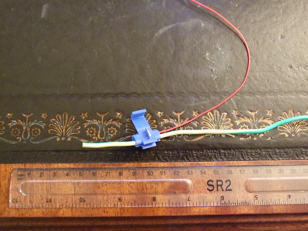
Mick, Yes, I am going for the multi level layout as I want to have a railway that runs in the landscape through valleys, over bridges and disappears and reappears from view. I will be able to combine gardening and the railway at long last. At present I am trying to concentrate on how to build the low breeze block walls and get the gradients correct over their length. Plus the flats sections flat. Sounds a silly thing to be focused on but my testing ( and your own experience) shows that to run 10 coach trains the gradients have to be even and as gentle as possible. I am going for 1 : 120 max. And to achieve this accuracy I have determined to purchase a laser level and have a point in the centre of my layout that I will use as the datum point. I have read that you can use the Roman method of getting things level : A garden hose with a plastic bottle at either end. Fix one end of the hose at your datum point and take the other end to where you want to mark the level. Make sure you fix this above ground level too. Fill the datum end bottle with water until you get the head ( height ) of water you require e.g 4 in above ground level. The water will fill the hose and the other bottle to the same head height. Voila you can check any point is at the same level as your datum reference. By adjusting the height of the datum bottle and filling as necessary you can vary the datum height. Clever these Romans. From my Datum point I will be able to use the laser level plus a long spirit level to check that my flat sections are indeed flat and that the gradients are consistent and as planned. So if you look back at my rough sketch what I am going to do is prepare a slightly more detailed master plan with all the datum points plotted so that when start to construct the trackbed I can keep everything as per the design. Probably sounds overkill but I know from making baseboards in the garage that even small height difference at the board joins plays havoc with the running. Si I feel that a bit of time spent getting the trackbed correct will pay dividents later. I read with interest that you had to plane a section of your decking boards as they had produced a "Hill" which was evident on the videos. My own test with 2 8ft boards produced a bump between the two boards so although the gradient was a nominal 1 : 120 the steam locos struggled with the bump! The diesels didn't seem to notice! I am going to use the breeze block and decking board method, like you Mick. I will tack my DCC bus to the side of the decking board and use cable lock connectors to take the bus to the dropper. See pic below :
-
Chris and Mick, The size of the wire needed for bonding the rail joins really only has to cope with a load of 1.5 amps max for OO. Even the droppers from your main DCC bus or main feed for DC would only need that. Why? Well for DCC you should have enough droppers to spread the load from your main 5 amp bus so that any one set of droppers and rail joins only has to feed one loco's power requirements. With DC it is the same as you only have one loco per section, so provided the wires can supply the max load that is OK. If you do get 2 locos ( double headed ) them the 1.5 amps is still enough as most modern Bachmann, Hornby and Heljan motors draw about 0.5 amps. The older Hornby can draw 1 amp so you might need to factor that in, especially if you have converted the older X04 and Ringfield motored locos to DCC ( and remember to get a chip rated high enough too! ) After all a house ring main is rated at 30 amps but you only use connecting flex rated at 13 amps for individual items. The max load on the WHOLE circuit is limited to 30 amps and the max item load is limited to 13 amps. So think of the main DCC bus as the ring main ( but at 5 amps ) and the individual items as the droppers rated at 1.5 amps max. I use the individual wires from a 13 amp multi core cable ( stripped out ) as my main bus as that gives me 13 amps capability plus good conductivity for longer feeds. I have read on other forums that the multicore type is better than the solid copper type as the multicore gives more cross sectional area hence reduced voltage drop. That will be a must outdoors to prevent voltage drop, I would think. My droppers are the normal layout wire but they are a max length of 2 ft so no problems with voltage drop there. My indoor garage layout uses the above methods and the bus run is 16 x 9 x 16ft fed from one end. No problems with the DCC main bus but I do run my Lenz set 90 at a 22v output. Regularly have 4-5 locos running at the same time ( bit of a juggling act but I am trying to use RocRail on my PC to automate some of that ) I have been frustrated by the lack of space afforded by my garage hence my moving outdoors and using a large shed for the fiddle yard and a branch line ( my current garage layout re-used and remodelled ) Can't wait to get things started outdoors and enjoy long trains lazily weaving through the mini landscape ( semi automatically I hope. ) Anyway I am hijacking you thread, so I will update my own in future.
-
Chris, Like the pictures of your progress - I have been inspired by everyones work so far. I hope you don't mind my saying this but I think you are giving yourself a headache with the soldering. The wires you are using are a little bit thick for the job and because of that they need a large hot soldering iron to supply enough heat to make a soldered joint. I think you could reliably drop down the wire size without any detriment plus you won't need to hold the iron onto the wire so long before it melts the flux and solder. A couple of tips to make the soldering easier : 1 - Use a glass fibre brush to clean the area of the rail you intend to solder. 2 - Always put flux on the wire and the rail before tinning. ( tin = apply solder to each ) 3 - Tin both the wire and the rail. 4 - Solder wire to rail adding flux to one side so solder flows. 4 - Keep the soldering iron head clean between soldering attempts. The secret to soldering is not trying to heat the metal to be red hot, you'll just melt everything plastic and end up trying to heat 2ft of rail! The flux allows the solder to melt quickly and flow so forming a bond. With everything tinned you should have enough solder on both wire and rail so as not to need any extra. It shouldn't take more that a couple of seconds when applying the iron to the items for everything to melt and join. It may be worth checking that you are using a solder suitable for electronics as these tend to melt at lower tempartures. This saves you having to hold the iron onto the items for too long. I use a little pot of flux and dip the wire in before soldering - you only need a tiny bit but it makes all the difference. Hope the above helps - I used to loathe soldering until I was shown how to do it properly and now its a breeze. You can even solder large 13amp cables by following the above steps ( but you need a big hot iron! )
-
All, As I am designing my Garden Railway I am faced with a decision as to whether the running tracks will be completely flat or whether to have a figure of 8 with a flyover. What should I assume to be the maximum gradient based on the following : 1 - Using Bachmann diesels pulling 8-12 coaches. 2 - Using Hornby & Bachmann steam pulling 8-12 coaches 3 - Goods trains as long as I can manage but would like 20+. My garden plot is about 40 foot by 35 foot so if I assume a difference of 4 inches for the flyover and a max gradient of 1 inch in 10ft ( 1:120 ) I can comfortably arrange my figure of 8 to allow up and down gradients so that the track is elevated by 4 inches at the cross over point ( flyover ) Are my assumptions reasonable? I attach a rough plan below : I think the crossover point at the bottom will need moving further left though to allow for the 1:120 drop and rise of both tracks. Grid is 5 foot to give an idea of scale and curve radii. The railway will run through a basically U shaped flower bed planted with alpines to keep everything small. The higher elevation track at the back based on the view from the shed. The area in the centre will be a grass viewing area. I wll probably have to have a lift out section the the right hand exit from the shed to allow access into the central area. Construction will be on blocks like Mike's, although not sure how high - trade off with working height inside the shed and amount of construction needed outside. I am thinking that 2 foot base datum would be Ok. This means the viaduct is about 2' 4" above the floor. Haven't done any costing apart from the shed, so might give myself a shock when I do that aspect!
-
Operating Points Outdoors
mainthreadmartin replied to mainthreadmartin's topic in Electrics & Wiring
Ian, Many thanks for the speedy reply. Yes, I had noticed a similar picture in your online photo album. Is the box simply made to fit over the top of the point motor as it sits on its base - looks like that from the photo. Is the box lined with any form of insulation? Apart from the siezure of the motor, do you get any problems with the peco point at all? What is the grease and where are you getting it from, if I can ask? -
Hi, I have been inspired to start the planning of my own DCC garden railway in OO. A quick question though :- is it possible to operate peco points outdoors reliably? Indoors I use the peco point motors without problem but not sure about how they will cope with the elements if outside. I suppose they could be hidden in lineside buildings and operated via the plastic rod supplied with the peco base. The main station I am going to house in a large shed so electrics for points and signals etc would be protected and in a permanently dry space. Similarly my Branch station would be indoors on the opposite side of the shed. The DCC main bus wires ooutside would be installed as part of the permanent structure, bonding all the sections and adding droppers to make sure I have a good DCC feed all around the layout. For the DCC control electrics I was considering creating a pluggable module which would contain the LS110/LS150 and possibly the Feedback modules - I use an LDT RS8. Having them as removabe pluggable modules would mean I could keep them indoors until I want to have a running session. They would be shower proof but not water proof. If it is feasable to have points outside then this opens up the scope to have an intermediate station with goods yard and passing loops etc. Would make the operations a bit more interesting. Long term I want to have some element of computer automation, hence the pluggable modules for the points, block detection and feedback. I know you don't have points on the SGR but do any of your other readers have any experience of using points outdoors? Thanks, Martin Head Nr Daventry.