Leaderboard


Popular Content
Showing content with the highest reputation on 05/10/2022 in all areas
-
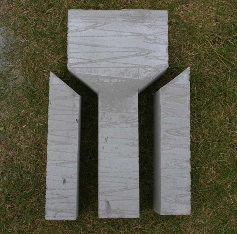
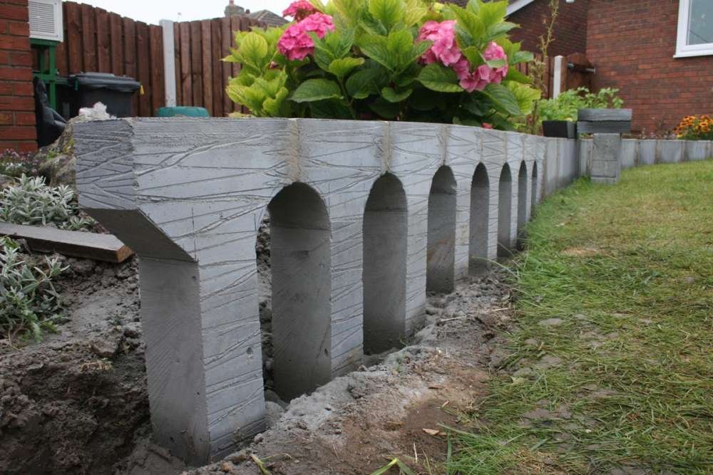
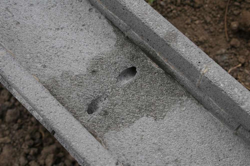
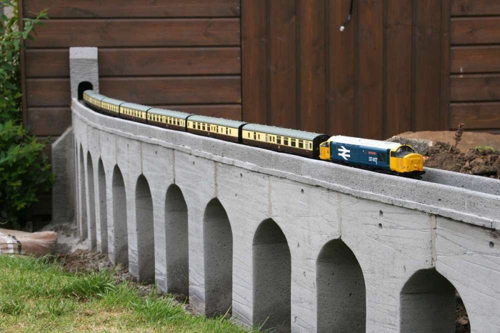
A STONE BUILT OO GAUGE GARDEN RAILWAY VIADUCT FOR LESS THAN THE COST OF A DECENT WAGON! by MICK NORFOLK For me one of the most fascinating aspects of model railways are the civil engineering structures such as bridges and viaducts. On an indoor layout these are typically constructed of card or other lightweight materials over a wooden framework or former and are often finished to a high level of detail. However, for an outdoor layout we need something much more resilient from which to build our structure, something that can withstand the rigours of extreme weather, and in my opinion one of the most durable and visually realistic products we can use is stone, or more accurately, a standard lightweight building block. An outdoor layout isn't normally finished to the same high level of detail that we have come to expect from a similar layout housed indoors and so construction techniques are often quite different. I would imagine there are very few indoor models constructed using a mixture of sand and cement, certainly none that would be easily transportable, but such materials are the minimum requirement for extended outdoor use. Although the technique mentioned here would be equally suited to the construction of a variety of bridges, for the purpose of this article we will be concentrating on the construction of a stone viaduct. However, before we take a look at just what's involved it may be of interest to look back at my earlier attempt at making an OO gauge model railway viaduct from plywood so that you can understand why I would now highly recommend the use of stone. Sounding much like the title to a classic song, back in the summer of 2009 I finally realised my ambition of one day being able to construct a large model railway layout and from the outset I had decided that the layout, to be located by necessity outdoors, had to incorporate a viaduct. I had never built a model railway before but decided that the viaduct itself would be constructed from exterior grade plywood. The photograph below shows that particular viaduct under construction despite the fact that it appears to be more in a state of demolition. As you can see from the above photo, the main structure of the viaduct was constructed from 9mm exterior grade plywood with the arches cut out using an electric jigsaw. Plywood spacers joined the two sides together creating the inner arch walls and short sections of plastic guttering formed the curved roof of the individual arches. The viaduct was constructed in two separate sections, the longer section consisting of 11 arches and the smaller section with just 5. A short over-bridge, designed to resemble that spanning a waterway, connected the two sections together into one long structure with an overall length of 10 feet 6 inches. The full extent of the viaduct can be seen in the following photograph, again taken whilst still under construction. In an effort to make the viaduct look more realistic and in order to help protect it from the weather, I decided to cover the facing side of the plywood with a thinly applied coat of exterior grade Polyfilla. This was done with limited success but while I was happy with my first attempt it was clear the the plywood structure would be susceptible to the rain and so whenever the layout wasn't in use the viaduct itself was covered by a large tarpaulin to prevent the track bed becoming waterlogged. The final photograph shows the Polyfilla covering I applied to the plywood sides which did give the effect of the stone structure I was looking for but also highlights my rather crude attempt at adding a girder bridge across the central span. Rather abruptly, an unforeseen house move meant that the entire layout had to be dismantled before it ever reached completion and the plywood viaduct itself was consigned unceremoniously to the local recycling depot. The good news was that the move of home enabled me to begin the construction of a new outdoor OO gauge layout, one that would again include a viaduct, but with previous experiences to hand it was decided this time to build in a more robust material. My first thoughts for a new viaduct were that it might be possible to cast one completely in concrete. I've seen descriptions of structures made that way before using wooden shuttering to constrain the concrete mixture and polystyrene block formers for the arches which are later removed once the concrete has set sufficiently but it seemed like a lot of work with no guarantee of a perfect finish. Could there be an easier way...? I had almost resigned myself to building a viaduct out of cast concrete when a member of the OO Garden Railway forum suggested the use of Thermalite blocks for the track base I was building at the time. The track base required raising just a few inches off the ground and concrete foundations to such depth would have looked unsightly and so following that member's advice I purchased several lightweight Celcon aerated blocks which were described as being suitable for outdoor use. I hadn't realised just how lightweight those blocks actually were, or how easily they could be cut using just an old saw. It soon became apparent that they could also easily be shaped using a coarse file or rasp. It was then that I had the idea of using this type of building block to construct my new viaduct. It would hopefully be structurally very sound and in addition it should be fully weatherproof. A number of lightweight standard Celcon aerated blocks were purchased from my local DIY superstore and at less than £1.40 each they ultimately proved to be a very economical way to build a substantial viaduct structure. I decided to use the blocks in their upright position standing them on their shorter edge. The central section of each block would form a viaduct pillar and a narrow section from the lower two-thirds part of each edge would be cut out to create an half-arched shape leaving the cut block resembling the letter 'T'. The photograph below indicates where those cuts were to be made: As already mentioned, the blocks can be cut with very little effort using an old handsaw but that's just my personal tool of choice and I would imagine that most other types of saw would be equally suitable. A straight cut is made with the saw from the base of the block up to the line previously marked some two-thirds of the way up the block before an angled cut is made from the edge of the block to the recently cut line enabling the edge section of the block to be completely removed. You should eventually end up with something like this: The 2 edge sections can be put to one side - you might find a use for them later. Once you've completed a few more blocks and placed them side by side you'll find you have something that's just beginning to resemble a viaduct type structure. Okay, it's not quite a viaduct just yet but I'm sure you can see we're getting somewhere. How you progress from here is a matter of personal preference but I'll describe the way I chose and leave you to decide what's best for yourself. In a similar way to building a brick or block wall stand the cut and shaped block on end and cement the next block up to it. If your ground is soft then you may need to add a shallow concrete footing to prevent later ground movement disturbing your viaduct but because my ground was very rocky I simply added a good layer of mortar around the base of the pillars to secure them in place. You may find that one of the modern contact adhesives is sufficient to hold the blocks securely together at the top but in this instance I chose to mortar them in position. As you can see above, the first 5 blocks have been cemented in place with a narrow mortar gap between them whilst one full block on edge simply prevents any sideways movement until they have thoroughly dried. The base of the pillars is packed around with a mortar mix to hold them securely. Once the blocks have dried you are left with a very solid structure and you can begin using a coarse file or rasp to round out each individual shaped archway. Continue adding further blocks and rounding out the arched shapes for the full length of your viaduct. The more blocks you cement together the more impressive your viaduct begins to look, especially from the more unusual viewing angles. To improve the appearance of the flat top of the viaduct I cut small individual sections of aerated block and glued them in place to create a narrow overhanging ledge and rising sidewalls. These can be seen in the above photograph before being easily shaped using nothing more than a sheet of sandpaper. To prevent the top of the viaduct becoming waterlogged, drainage holes were drilled at an angle downwards through the top of the viaduct so that they emerged on the sidewalls above each viaduct pillar. Once completed the whole viaduct was then treated with a water repellent solution suitable for application to bricks and blocks in order to limit water ingress. You can see where the drainage channels, drilled at an angle into the top surface, emerge through the sidewalls of the viaduct at the top of each pillar in the photograph below. If all goes to plan you should end up with a very solid viaduct that will withstand all that winter has to throw at it without the need for the protection of a tarpaulin covering and be ready for running again the following Spring. Mick The above text and accompanying photographs are the copyright of the author, Mick Norfolk, and should not be reproduced without prior permission.
 1 point
 -
No not at all. I'm probably in the minority when it comes to not being all that concerned about liveries and allocations and to be perfectly honest I'm modelling something in the garden that I know very little (aka nothing) about. I've never been on a train in Scotland in my life but I just try to recreate a sense of the single line through remote surroundings with the reverberations of class 37s!! The attic layout is a slightly different story but even up there ANY class 56, 58, 60 is fair game for the MGR workings, though I don't allow 60s on HTA's as that was after my time. The first steps always the hardest as they say but Iain's right, start with acrylics and you can remove it quite easily if it doesn't please you.1 point
-
Use acrylic paints and its easily removed if you don't like what you've done.1 point
-
Ah, now that makes perfect sense. I knew there had to be a reason and I guess if you cut them from one block it would either make the supporting piers too thick or to fragile for reliable support. I'm learning stuff everyday.1 point
-
Slight drift here, but... When I was a kid back in the 70's / 80's my uncle used to be the guy who repaired, overhauled and restored all the steam engines for Carters Steam Fair. Many a childhood winters day would be spent cycling over to White Waltham. First for a look around the airfield, then for a trip up on to the bridge to watch the trains going up and down the GW mainline before finally popping into Carter's place for some quick chat and if we were lucky a go on the shooting game. Happy memories...1 point
-
Sounds like you've had a busy day, look forward to seeing the pictures. Thanks for the answers to my questions above. Fair point about the sound on the ETHEL. I hope I don't come across as too anal about liveries, allocations, etc. It's just that it is that side that interests me in this hobby. When I eventually get the layout built it will be the operation of the right locos on the right trains and trying to figure out what locomotives I can use on which service after a simulated locomotive failure that will keep me going. Believe it or not I already have a full timetable with the locomotive diagrams and staffing duties worked out, with each depot's staff only 'signing' the correct selection of motive power etc. This also leads on to the correct formation of stock and locomotives in regard to braking etc. The big thing being when I'm forced to use a 'no-heat' locomotive on a service train. One day I might be as brave as you and pick up an airbrush once more. I did this back in my youth with very dyer results! I plan to operate the period from 1978-1993 so a two-tone green Bachmann class 25 that I picked up on ebay for £30 one Saturday morning will probably be the first candidate, although I will probably try with some old spare Lima bodyshells first.1 point
-
With a 5 year old being in control of trains outside, on a raised base where a derailment could be a bin bag job for the poor train involved, I got thinking we need some protection. I'll give our little boy credit, he's very mature for his age and treats the trains as models where as some of his friends might not be so gentle and on the ball. However, even I've had a near miss when a coach came free and I wasn't paying attention. I've looked at various solutions, most of which require purchasing something or another but decided to try and use things I already have. Plastic netting (left over from our Protectapet fence) Large cocktail sticks Outdoor fence paint Cable ties Staple gun and staples Due to the way the plastic netting bends the outside of the corners only requires a couple of posts to keep it tight. The inside requires double. It might not be the best looking but providing the cocktail sticks hold out it will require no maintenance.
1 point
-
From the album: The Pickle Line
1 point -
Who would have thought that India Pale Ale would work like that? 😉1 point